The order of exhaust components changes what each downstream unit receives. A diesel oxidation catalyst can alter the gas before it reaches a filter; a filter removes soot before gas continues toward later treatment; an SCR unit needs conditions suited to NOx reduction.
Those functions make placement consequential, yet they do not create one universal layout for every engine. For a diesel particulate filter system, the design question is which temperature, pollutant mix, and available space each component will face along the chosen path.
Follow the Exhaust, Not a Fixed Diagram
A DOC oxidizes CO, hydrocarbons, and soluble organic fractions. It can also affect the NO₂/NOx balance and exhaust temperature, which may influence downstream DPF regeneration and SCR chemistry. A DPF has a different assignment: it captures particulate matter.
An SCR unit uses a reductant to convert NOx. If a component is moved, the next unit receives a different gas and thermal history, even when its own construction has not changed.
For illustration, place a DOC ahead of a DPF and an SCR stage farther downstream. That sequence can give the filter an oxidized upstream gas and reserve the NOx reaction for a later unit.
It is an example of how functions may be linked, not a rule established by the supplied DPF page. Other packaging or operating constraints can change the discussion. The order needs to be evaluated at the actual temperatures and pollutant rates throughout the engine’s duty cycle.
Position also changes the opportunity for heat to reach each element. A unit farther along the line may see a different temperature from the engine outlet because upstream equipment and pipework alter the gas.
Regeneration needs enough heat at the filter, while SCR chemistry and dosing depend on conditions at the catalyst. A diagram that names components but omits sensor positions and temperature data cannot settle the placement question. Flow and available mounting space belong on the same drawing.
Place the Filter Where Its Operating Cycle Works
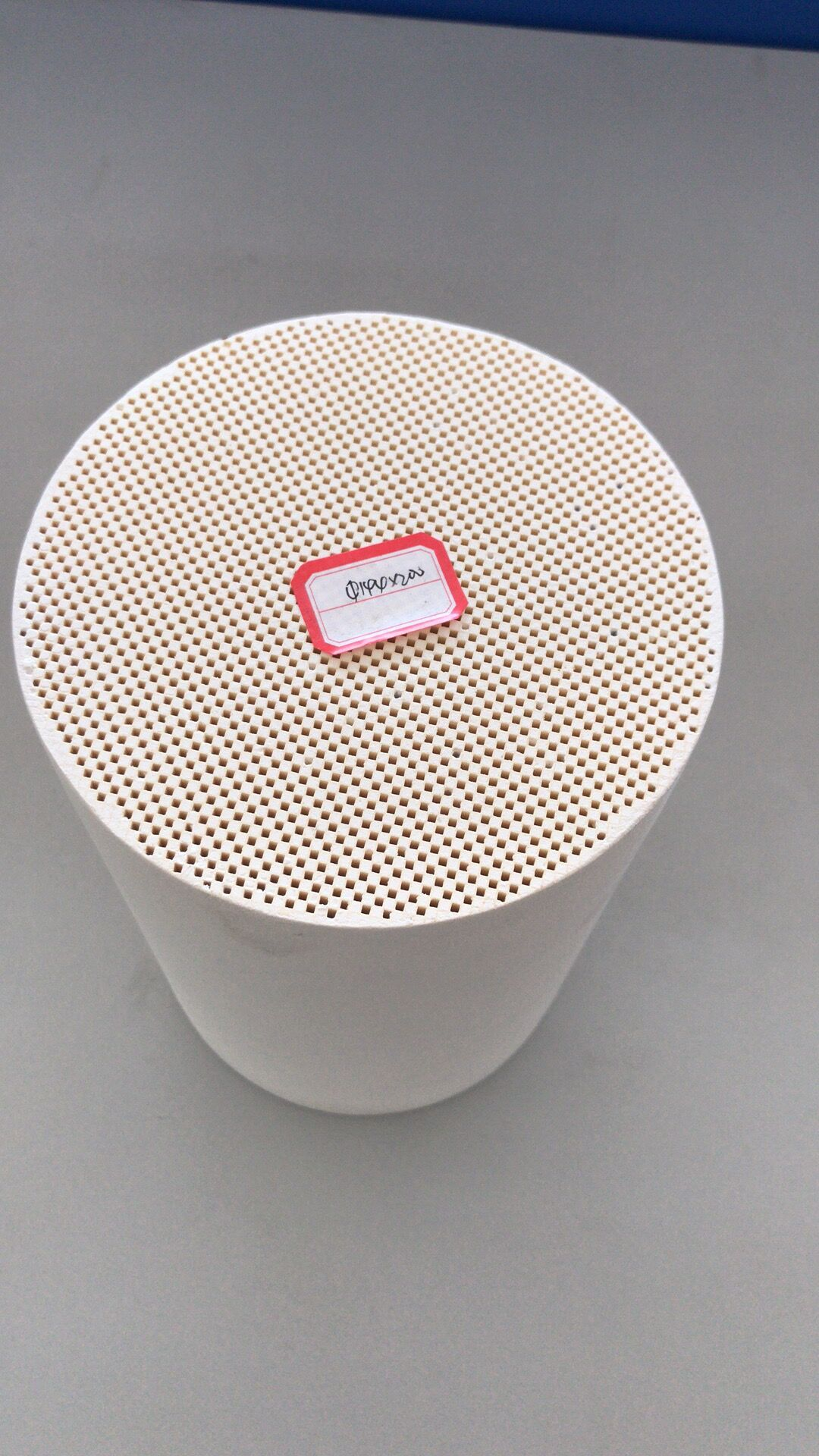
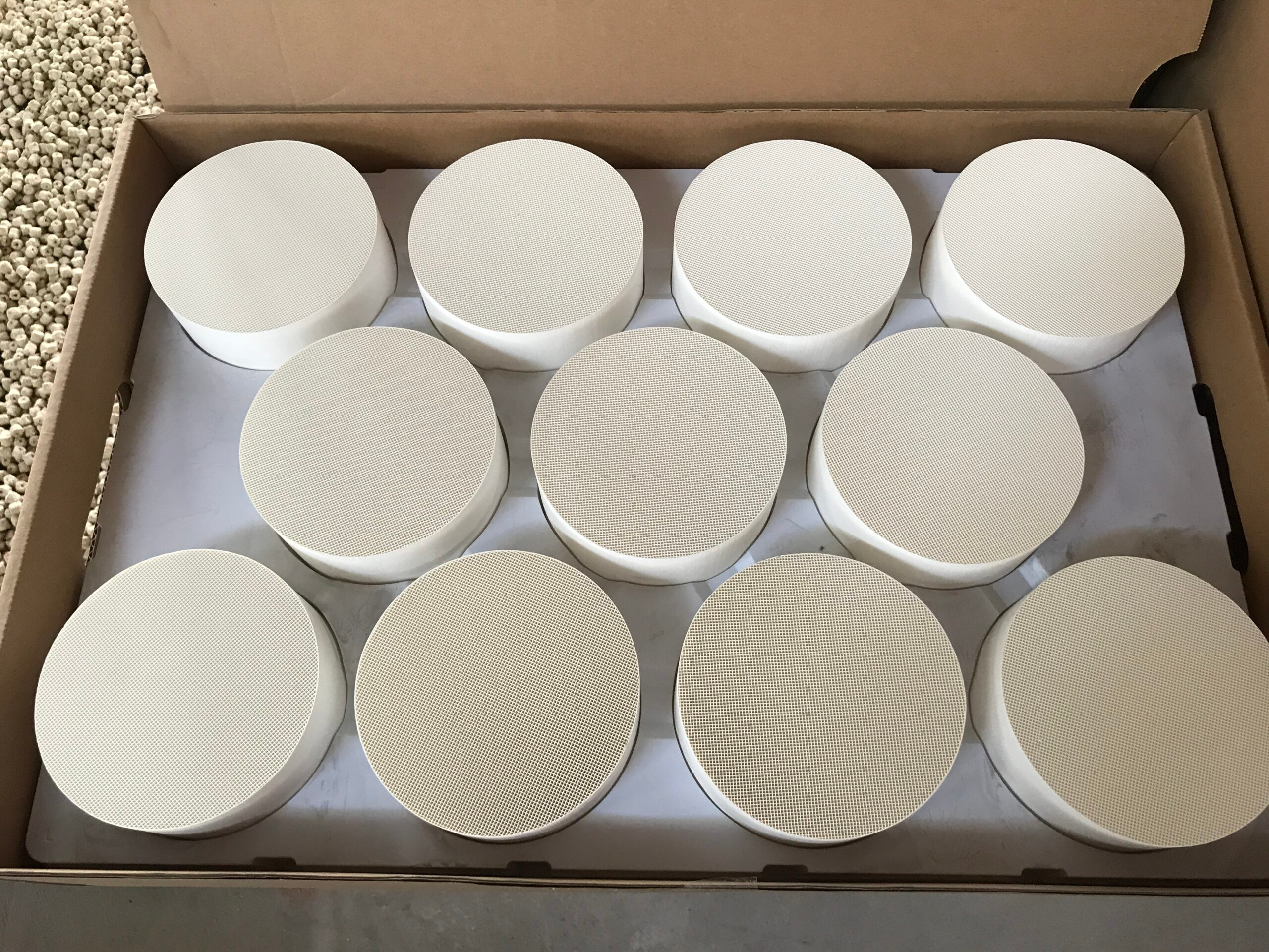
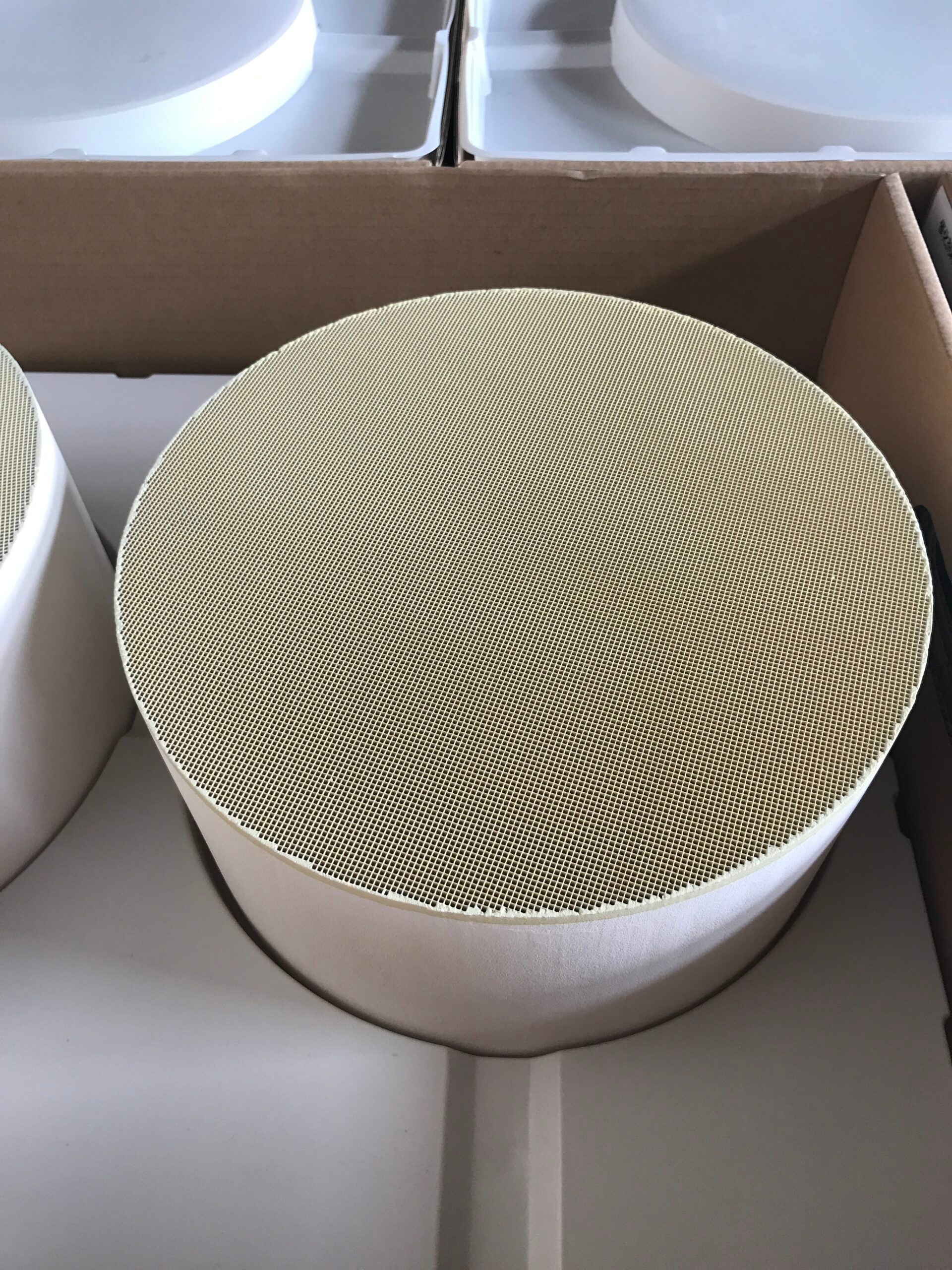
The ceramic monolith in a diesel particulate filter system uses a wall-flow path: alternate channel ends are blocked, so exhaust crosses porous walls and particulate matter is deposited there. Capture raises the need to manage soot loading and regeneration.
If the filter is moved, the temperature available for regeneration and the composition of gas entering it may change. Both clean and loaded pressure loss should be considered when judging a proposed location.
The filter’s thermal and packaging duties determine which of our Hualian Catalyst DPF configurations is worth evaluating. Cordierite or SiC cores are available in round or square form, with customizable size and 100, 200, 300, or 350 CPSI.
Our supplied page states filtration efficiency above 99% for solid matter and above 90% for total diesel particulate matter, and it lists regeneration capability. Those figures describe filtration under the source’s stated product context; they do not establish a DOC-DPF-SCR order or guarantee the same installed result for every engine.
A diesel particulate filter replacement is consequently more than a match to the old can’s outside dimensions. Material, cell density, connection shape, allowable pressure loss, and regeneration conditions all affect whether a new filter fits the existing system.
If the upstream DOC or downstream SCR has changed, the replacement inquiry needs the current line layout as well as the engine data. The filter specification should be checked against the arrangement it will actually enter.
Check What the Next Component Will Receive
SCR operation depends on the NOx mix, reductant supply, and temperature at its own location. A DOC placed earlier can alter the NO/NO₂ ratio, but the effect depends on operating conditions and the rest of the exhaust line.
A DPF can remove particulate matter before the gas reaches the SCR stage, while its regeneration events can change thermal conditions. These interactions explain why component order is a system decision rather than three independent product choices.
A placement rule cannot be inferred from the DPF sheet alone. Its documented scope is wall-flow construction, filtration, Cordierite or SiC materials, CPSI options, and regeneration; DOC and SCR positions require engine-level flow, emissions, temperature, and control data. For that reason, we would map the filter’s duty first and test any proposed component order in the assembled line.
A diesel particulate filter system can be mapped through measurement points before and after each unit. Inlet and outlet temperatures show what heat is available at the DOC, DPF, and SCR positions.
Particulate, NOx, and pressure readings identify which component is being asked to handle which load and whether an upstream change reaches downstream. The measurements need to be taken over relevant engine states, including low-load running and filter regeneration, rather than at one convenient steady point. That record gives a placement proposal a testable basis.
For a diesel particulate filter system, the useful output of a placement study is a component-by-component map of inlet conditions and intended function. That map can also guide a diesel particulate filter replacement when the rest of the line is retained.
Our DPF options address the specified envelope and duty. Whether the proposed order works is a measurement question for the assembled aftertreatment system. Each component needs the gas conditions its assigned reaction or capture task requires.