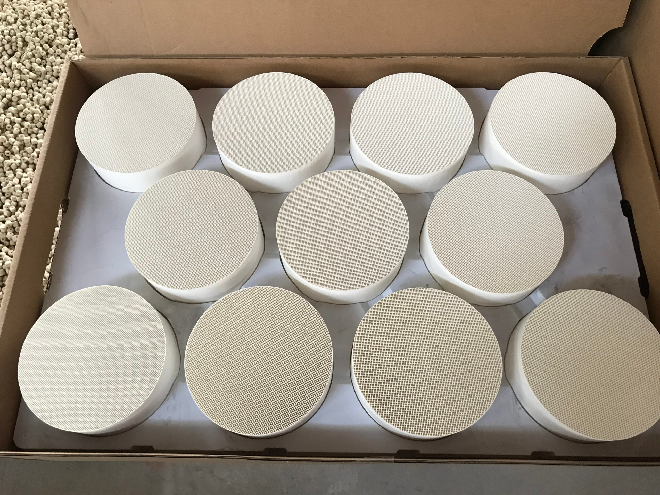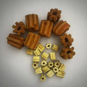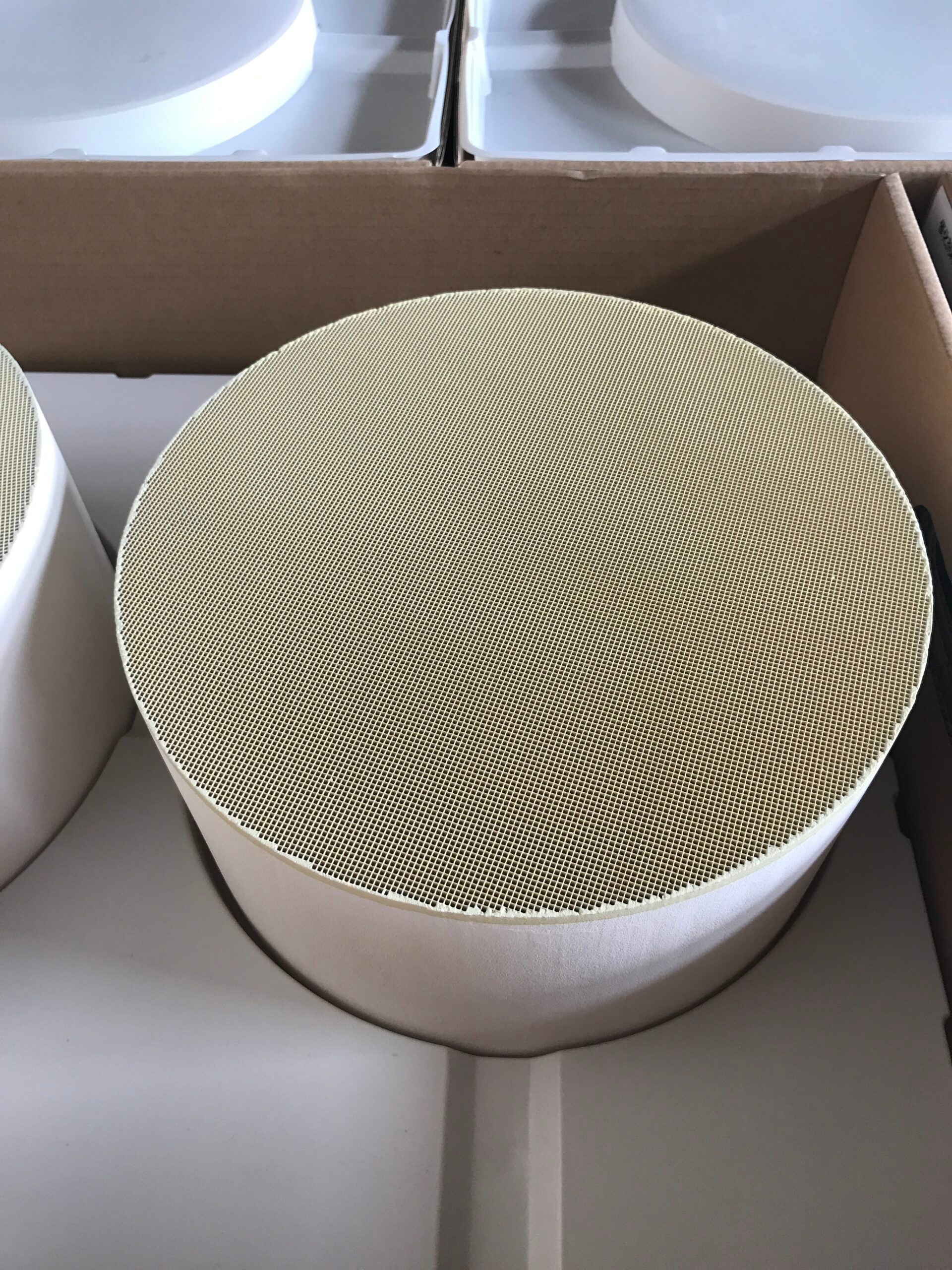
A ceramic honeycomb filter must expose a large internal area without imposing excessive flow resistance or losing integrity as exhaust temperature changes. Its channel duty determines what that area accomplishes.
A wall-flow filter directs gas through porous walls and retains soot; the ceramic DOC in the supplied product information keeps channels open so gas can reach a catalytic coating. Their common honeycomb form therefore calls for two different assessments of contact, pressure loss, and thermal stability.
Follow Gas Through the Channels
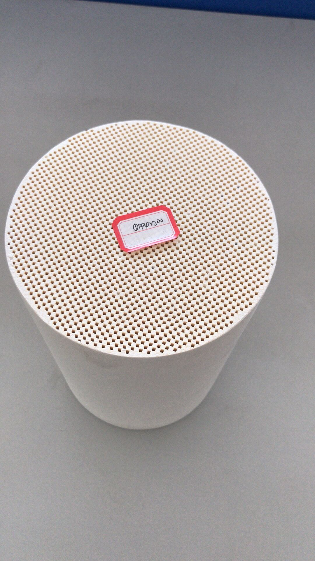
In a wall-flow honeycomb ceramic filter, alternately blocked channel ends force exhaust through porous walls. That wall area forms the capture route, while wall thickness, channel length, soot loading, and gas flow affect resistance.
A flow-through ceramic DOC instead presents coated channel walls to gas moving along open passages. More cells per square inch changes the geometry in either case, but it cannot establish filtration or conversion without the corresponding material, coating, and operating conditions.
Open channels are especially relevant to a diesel oxidation catalyst. Gas can pass along the walls as CO, hydrocarbons, and soluble organic fractions encounter the active coating. A wall-flow filter closes alternating channel ends and makes gas cross a porous wall to capture particulate matter.
The difference explains why a ceramic honeycomb filter cannot be evaluated from the word honeycomb alone. The route through the core must be specified before pressure loss or filtration claims are compared.
The geometry also affects how evenly exhaust is presented to the active surface. If flow concentrates in one region, some channels carry more of the duty while others contribute less. Installation, inlet shape, and substrate dimensions therefore matter alongside CPSI.
A nominally large contact area is most useful when the exhaust actually reaches it under the engine’s working flow. That is a design and validation question, rather than a property proven by a cell count in isolation.
Balance Pressure Loss With Contact Area
The pressure difference across a honeycomb ceramic unit is influenced by passage size, length, flow rate, and the condition of its surfaces. Narrower passages or a longer flow route may increase contact opportunity while also raising resistance.
The objective is not the greatest area at any cost; the engine still has to move exhaust through the unit. A comparison of candidate substrates needs both pressure data and conversion data at corresponding flow and temperature points.
The flow-versus-area choice enters our Hualian Catalyst DOC specification before a shape is selected. Ceramic and metal substrates can be made round, oval, or racetrack, in customizable sizes and 200, 300, 400, or 600 CPSI.
We describe the structured ceramic substrate as offering high catalytic contact area, low pressure loss, and thermal stability. The installed result depends on the chosen size, coating, and engine conditions.
Shape is more than an external styling choice. A racetrack envelope may suit a flat mounting space, while a round part may suit a cylindrical can. The available cross-section and length influence channel count and gas velocity, which in turn affect contact and pressure loss.
A 600 CPSI substrate in one size cannot be judged against a 200 CPSI substrate in another size without stating their actual flow areas. The complete geometry gives CPSI its engineering context.
Track Thermal Stability Through the Operating Cycle
A ceramic honeycomb filter faces heat changes during acceleration, idle, and regeneration. In a wall-flow core, retained soot and its removal make thermal exposure part of the filtration duty; the porous route must remain intact as conditions shift.
The flow-through DOC discussed here faces a related but distinct task: retaining an open passage and an effective coated surface. Thermal stability does not assign every ceramic formulation or coating the same temperature limit. The relevant cycle and selected product specification still govern the application decision.
Thermal behavior is better described by a sequence than by one peak value. Warm-up, sustained load, and cooling expose the honeycomb ceramic core to different gradients and contact conditions.
Pressure loss and oxidation can be compared at equivalent points before and after those cycles to see whether the chosen geometry still serves its duty. A stable core is the physical foundation for the DOC, but the activity of its coating needs its own evidence under the same exhaust conditions.
In our DOC description, oxidation of CO, hydrocarbons, and soluble organic fractions can also raise the NO₂/NOx ratio and exhaust temperature. Those changes may support downstream DPF regeneration and fast-SCR operation.
The DOC does not itself become a particulate filter or an SCR reactor by supporting them. Its value in the line comes from its own oxidation function and from the conditions it passes to the next component.
For a ceramic honeycomb filter inquiry, the first drawing should distinguish an open-channel oxidation catalyst from a wall-flow soot trap. Filter assessment then needs its porous-wall route, soot loading, regeneration heat, and pressure allowance.
For the DOC discussed here, we would compare envelope, exhaust flow, temperature, CPSI, and oxidation duty. The honeycomb ceramic structure is suitable only when flow and thermal evidence match the job assigned to that particular core.