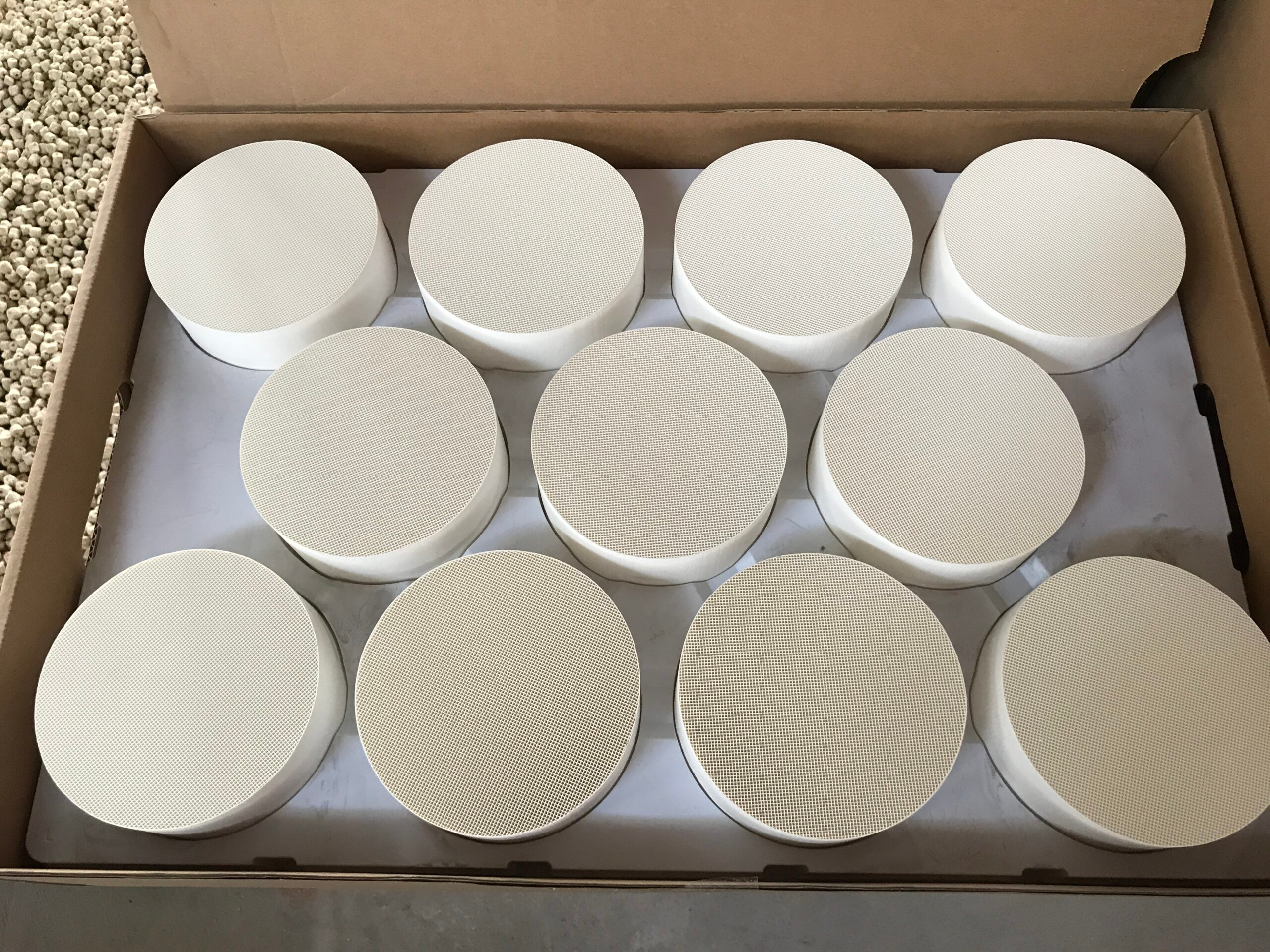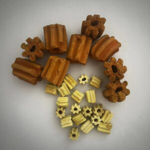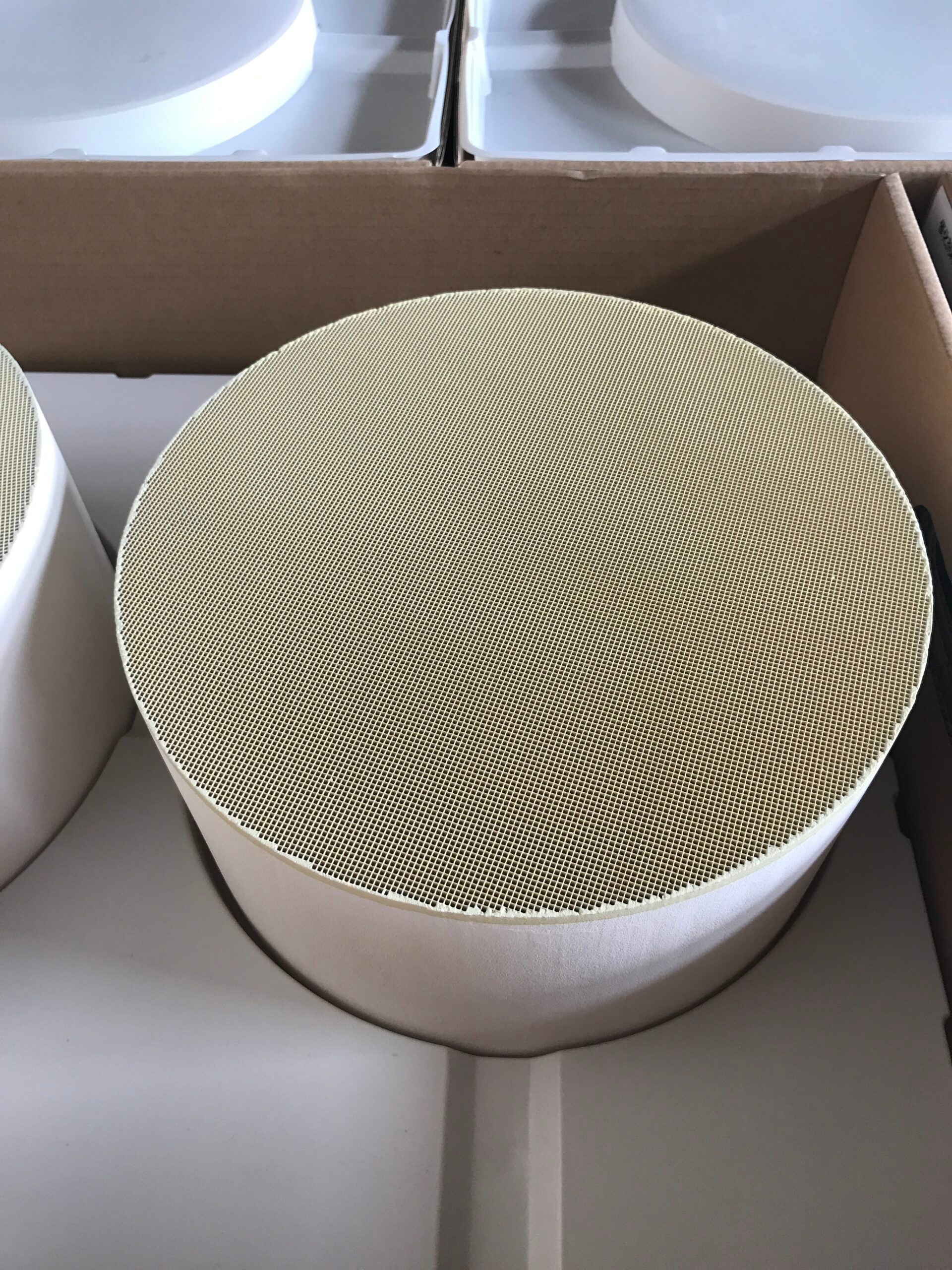
Exhaust gas does not react with a catalyst simply because it passes through a housing. Molecules must reach an active surface, spend enough time near it for the relevant reaction, and continue through the device without excessive resistance.
The support structure influences all three conditions. Channel size, shape, and available surface area can improve gas-to-catalyst contact, but they also change velocity and pressure loss. Understanding that tradeoff is a better starting point for support design than asking for the greatest possible surface area in isolation.
Follow the Gas Through the Support
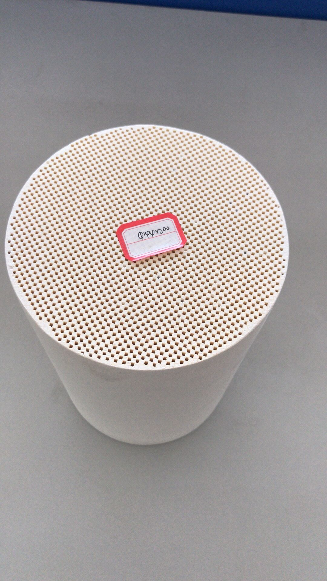
Mass transfer describes the movement of reactants from the flowing gas toward the catalytic surface. In a structured support, channels create a defined path and expose a coating to the stream. The amount of exposed area matters, but so does the distribution of flow across that area.
Gas that favors a few channels may leave other surfaces underused. At the same time, a channel must remain open enough to carry the expected volume of exhaust through the available space.
A catalytic converter manufacturer can adjust dimensions and shape to address these conditions, but a change to geometry seldom has only one effect. Reducing channel width, for example, may increase surface available within a given frontal area while making the path more restrictive.
Increasing the frontal area may lower velocity but require more installation space. The appropriate design question is how much contact the reaction needs under the real flow and temperature range, not whether one geometry looks more sophisticated on paper.
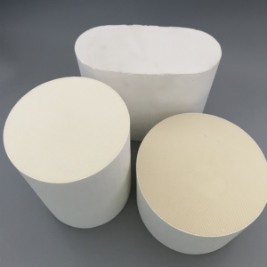
For catalytic converter manufacturers working across DOC, DPF, SCR, and other products, the same word “support” can hide different flow paths. A DOC or SCR typically relies on gas flowing through coated channels, while a wall-flow DPF directs gas through porous walls to retain particles.
We do not compare these structures using area alone. Their intended functions change what the pressure drop and mass-transfer discussion must include.
The inlet and outlet geometry deserve attention as well. If gas enters one portion of the support more readily than another, the nominal channel count will overstate the area used effectively.
A flow-distribution issue can then be mistaken for a coating problem. Looking at the whole passage from inlet to outlet keeps the discussion tied to the conditions the active material actually experiences.
Read Pressure Drop Together With Reaction Conditions
Pressure drop is the loss of pressure as gas crosses the component. It reflects channel geometry, length, flow rate, and, in some applications, material deposited during use.
A design with low initial resistance is useful only if the gas still reaches the active surface under operating conditions. Conversely, maximizing contact without considering backpressure can burden the exhaust system. Neither measure gives a complete account of performance by itself.
The reaction adds another dependency: temperature and gas composition can change how much conversion is possible even when the support geometry remains unchanged. A catalytic converter manufacturer therefore needs information about the engine or process, target pollutants, expected flow, and available envelope before choosing a structure.
A geometry that works at one flow rate may behave differently at a higher load, when velocity rises and the time available for contact falls.
There is also a manufacturing constraint. Thin walls, small channels, unusual shapes, and coating choices must survive production and the operating environment. Treating pressure drop as a single number can obscure these practical limits. A better comparison reports the tested or simulated conditions behind the number and checks whether those conditions resemble the intended application.
Turn the Tradeoff Into an Engineering Specification
Our engineering work at Hualian Catalyst starts with specification review and requirement analysis, followed by solution and emission-reduction simulation. Our product scope includes DOC, DPF, SCR, VOC, and metal-monolith catalytic-converter parts.
That breadth does not make one support design suitable for every duty; it gives us different structures to consider when the customer defines flow, pollutant target, dimensions, and system constraints. Through OEM/ODM work, we can develop customized dimensions, shapes, coatings, and related system requirements.
The useful output from a design discussion is a set of linked limits rather than one preferred feature. Specify expected flow range, allowable pressure loss, operating temperature, target reaction or filtration duty, and available installation space.
Then examine what happens if a channel, coating, or overall size changes. For catalytic converter manufacturers, those linked questions reveal whether a proposed gain in contact comes at an unacceptable flow or durability cost.
Testing completes this comparison. Because our workflow covers design, development, manufacturing, testing, and after-sales support, we can discuss the chosen configuration against the agreed specification rather than a generic benchmark.
If the test condition changes, the interpretation should change with it. Reaction efficiency, mass transfer, and pressure drop are not three independent scorecards; they describe different consequences of the same physical design.
Support geometry is best judged by the flow and reaction it must manage in service. A useful design leaves room for gas to move, exposes enough active surface, and fits the temperature and packaging limits of the application.
At the intended flow, support geometry is resolved by the measured balance between gas access to active sites and pressure loss through the channels.