A 400 CPSI converter can have an acceptable pressure loss on its own and still sit in an exhaust line with excessive total backpressure once a DPF is included. Cell density describes the honeycomb’s channel count, not the resistance of every component downstream.
The filter adds its own flow restriction. This restriction increases as particulate matter accumulates. Managing the combined system requires a pressure budget tied to exhaust flow and filter condition. The question is not whether 400 CPSI is inherently high or low. The question is how that geometry performs with the chosen dimensions, foil thickness, and DPF arrangement.
Put 400 CPSI in Its Geometric Context
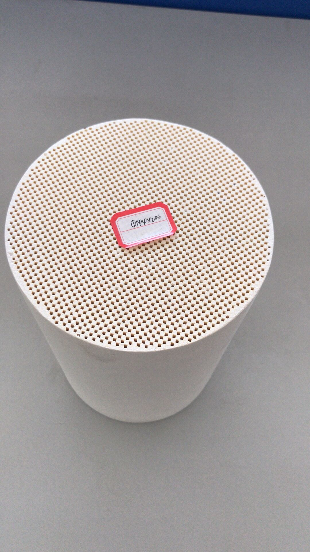
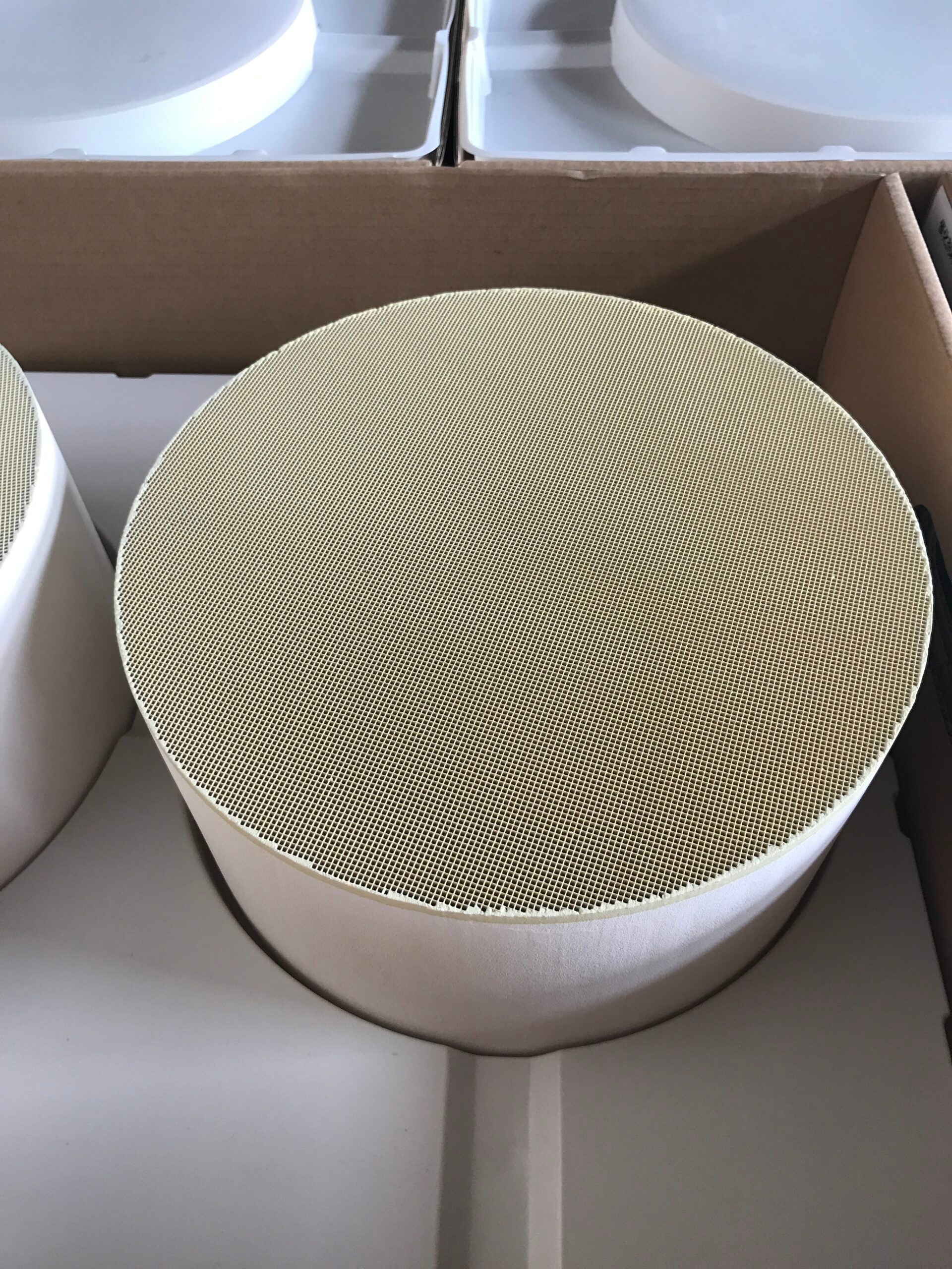
Four hundred cells per square inch describe the density of channels across a substrate cross-section. The available flow area also depends on wall or foil thickness, diameter, length, and the coating applied to the passages.
Two 400 CPSI parts can therefore impose different pressure losses even before a filter is added. Their inlet and outlet designs may distribute gas differently as well. The number is a useful geometry descriptor, but it cannot predict backpressure on its own.
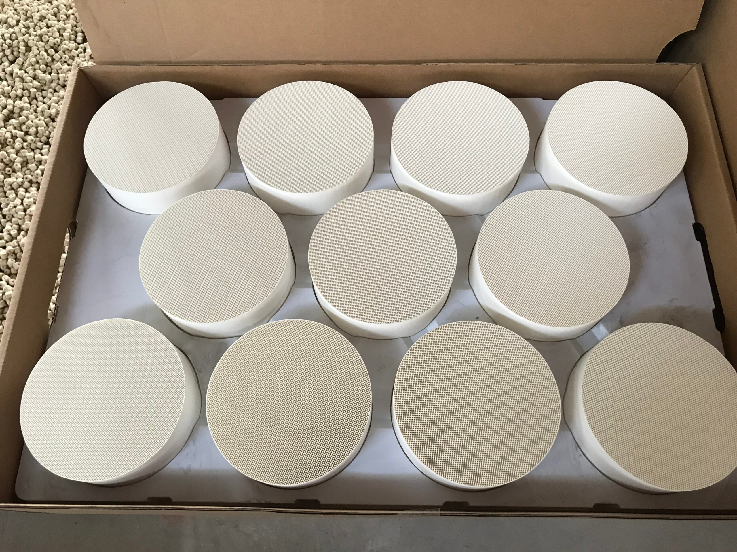
A 400 cpsi catalytic converter may offer a different contact-and-flow balance from a lower-density option in the same envelope. More channel walls can increase available coated surface, while narrower passages may raise resistance. The actual effect depends on exhaust volume and the overall substrate construction.
If a metal substrate is made larger or shorter, the pressure result can change without any change to CPSI. That is why a fair comparison names the whole part and the test flow rather than comparing only cell labels.
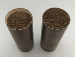
For a metallic catalytic converter, thermal and mechanical properties can also influence the chosen geometry. Thin-wall construction is used to reduce exhaust resistance, but wall thickness is not the only variable.
A technically useful specification includes the operating flow range and the physical envelope allowed for the substrate. The conversion task still requires coated contact, so reducing resistance cannot be the sole acceptance criterion.
Account for Foil Thickness and Dimensions
A 400 CPSI option sits within the 50–600 CPSI metallic honeycomb range we list at Hualian Catalyst. Our stated diameter range is 28–550 mm, with length up to 300 mm. Foil thickness options are 0.03, 0.04, 0.05, 0.06, 0.08, and 0.10 mm.
These figures describe configurable dimensions and construction features, not measured backpressure for every combination. The thinner-wall approach is intended to keep exhaust resistance low, but the installed result depends on which options are used together.
Changing foil thickness alters the space left open within a channel and the material available to form the wall. Diameter changes the frontal area through which gas enters; length changes how far it travels along the coated passage. The effects interact.
Two 400 CPSI converters with different diameters or foil thicknesses should not be assumed to have the same pressure loss. The CPSI label alone does not determine the result. The relevant comparison specifies the complete geometry and the flow at which it was assessed.
The metallic catalytic converter is only one portion of the system pressure budget. Bends, pipe diameter, and other components add resistance. In an installation that also includes a DPF, the filter’s condition matters: a clean filter and one carrying soot can present different loads.
The converter geometry can be optimized only with that wider exhaust path in view. A low converter pressure drop cannot guarantee that the assembled system stays within its allowable limit.
Separate Converter Loss From DPF System Loss
A combined pressure assessment needs measurement points or a model that distinguishes the converter from the filter and the remaining pipework. The DPF’s particulate-capture duty introduces operating states that a converter alone does not have, including soot loading and regeneration.
If total backpressure increases in service, we cannot assign the cause to the 400 CPSI substrate without first examining soot loading and regeneration states. That distinction matters for both design changes and maintenance decisions.
A metallic catalytic converter in a combined line needs two pressure records: its own loss at the stated flow and the DPF’s clean and loaded losses.
Our metallic-honeycomb information lists CPSI, dimensions, and foil thickness; it does not include a measured pressure-loss curve for the chosen filter. Installed backpressure can be assessed only after those component measurements are brought together under matching flow conditions.
Conversion also remains part of the decision. A lower-resistance passage might change contact with the active surface, while a denser structure might change both contact and pressure loss.
Evaluating candidates at matching flow rates, temperatures, and emission conditions keeps that tradeoff visible. The objective is not to minimize one pressure reading at any cost; it is to meet the exhaust system’s flow allowance while supporting the required treatment duty.
Four hundred CPSI is a starting description of the converter’s channels. Diameter, length, foil thickness, coating, and the DPF’s operating state determine what that number means in the installed line. The 400 CPSI label gains practical meaning only when converter loss and the filter’s changing load are measured separately in the assembled line.