Space for an exhaust component is rarely a clean cylinder. Floor panels, frame members, heat shields, or neighboring pipes can limit one dimension while leaving room in another. A flattened converter profile may fit such an envelope, but the outer shape is only the first design consideration.
Exhaust still needs a workable passage through the core, and the assembly has to tolerate heat and movement after installation. The useful starting point for a flat catalytic converter is therefore a dimensioned space claim: which surfaces are fixed, where are the connections, and how much flow area can the package retain?
Start With the Installed Envelope
An exhaust drawing should show the space available around the component, not simply the maximum width and length of an empty cavity. Mounting points, inlet and outlet directions, service access, and clearance from nearby parts all reduce usable room.
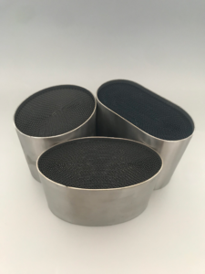
A metallic catalytic converter can be built to a customized geometry, yet a shape that fits during assembly might be difficult to remove or protect from heat in service. The installation envelope is a functional constraint, not a cosmetic preference.
The word flat can describe several cross-sections. An oval or racetrack shape may use width where height is scarce; another custom profile may be required when the route bends or narrows. None of these labels specifies the internal flow area on its own.
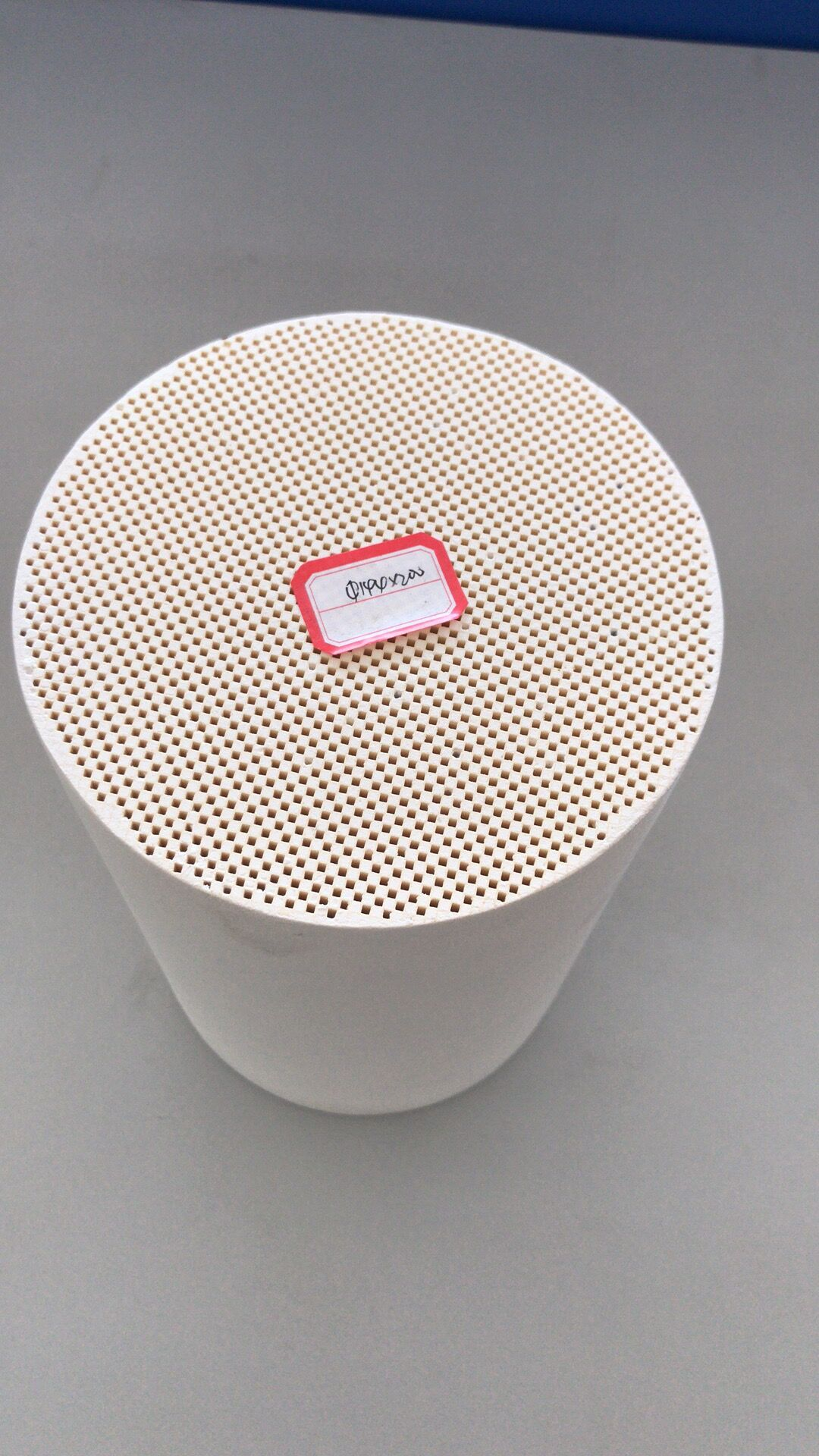
Wall construction and the metal honeycomb core determine how much of the outer package remains open to gas. Before committing to tooling, the design needs a drawing that distinguishes external clearance from the space available inside the housing.
Connections also matter. If the inlet directs exhaust sharply toward one side of a flattened core, some channels may receive more flow than others.
A larger nominal face area will not deliver its full value if gas distribution is uneven. The exhaust route leading into and out of the part must therefore be discussed together with the converter outline.
Keep the Flow Path Useful After Reshaping
Changing the cross-section shifts the relationship between frontal area, channel length, and housing transitions. A narrow height might be offset by greater width, but the inlet and outlet still have to distribute gas across that width.
The metallic catalytic converter must offer enough coated contact for its treatment task while staying within the system’s pressure-loss allowance. A package that looks generous from outside can still restrict flow if the internal passage or end transitions are poorly matched to the engine.
Cell density adds another dimension to that tradeoff. CPSI changes the number and size of channels across the core, but it does not reveal the result without overall dimensions, coating, and test flow.
A flat catalytic converter designed for a tight cavity may need a different combination of frontal area and CPSI from a round unit serving the same engine. Such changes have to be assessed as a whole rather than inferred from one parameter.
The process also includes manufacturing feasibility. A custom shell and core must be held in the intended shape, joined to the exhaust connections, and inspected against the approved drawing.
If the envelope changes late in the project, the internal geometry and pressure estimate may need revision. A controlled drawing makes that revision visible to both the design and production teams.
Match Material and Construction to the Tight Space
Round, oval, racetrack, and other customized geometries are options in our Hualian Catalyst range once the installation envelope and connection positions have been established. For a flat converter drawing, our listed 28–550 mm diameter span and 300 mm length ceiling are starting dimensions to reconcile with the available envelope.
We use a FeCrAl metal honeycomb core with stainless-steel shell options, and size, CPSI, and coating can be customized. These figures identify available design variables; they do not mean every possible flattened profile or every combination has already been validated for a specific exhaust system.
The metal construction is presented as compact, strong, and heat-resistant. In a constrained installation, strength and heat tolerance are relevant because mounting and nearby components may leave little freedom to move the part.
Mechanical loads and thermal clearances still need to be considered in the actual assembly. A metallic catalytic converter that fits the space but places a connection under undue strain would not solve the packaging problem.
For a custom proposal, we would need the installation drawing, allowed clearances, connection positions, exhaust-flow range, and treatment requirement. A flattened shape can then be compared with oval, racetrack, or other feasible cross-sections.
Pressure loss, effective channel area, coating requirements, and assembly access belong in that comparison. The decision is not whether a flat outline is possible; it is whether that outline leaves the converter able to do its job.
Space-constrained design succeeds when external fit and internal function are resolved together. Our metal-core dimensions and customization options provide a starting range, while your drawing defines the actual boundary A flat catalytic converter is suitable only when its installed geometry, flow path, and treatment function can all be verified against the same specification.