At peak exhaust flow, a converter may offer sufficient catalytic activity in theory, yet still impose too much resistance on the engine. Opening the flow path may reduce that burden, but it can also change how gas reaches the active surface.
A high-flow design therefore has two measurements to answer for: pressure loss and treatment performance under the same operating conditions. Neither an oversized housing nor a low-backpressure claim alone resolves the problem. The work begins with the engine’s flow range, available installation space, and emissions duty, then examines how geometry and substrate choice affect both outcomes.
Set the Flow Target Before Enlarging the Part
Exhaust volume changes with engine speed and load. The converter must carry the highest relevant flow without creating unacceptable backpressure, while still providing adequate treatment during the rest of the duty cycle. An installation with fixed housing width shifts the flow discussion to channel geometry and inlet transitions.
A shorter substrate may also ease resistance, yet it changes the length of the coated path. These options have different consequences, so the flow target must be stated together with its corresponding operating point.
Within a diesel oxidation catalyst system, the DOC has a chemical task as well as a hydraulic one. Gas must contact a coated surface at a useful temperature for the target oxidation reactions.
If a design change makes the passage easier but reduces effective contact, the apparent flow improvement may come at the expense of emission treatment. Conversely, a tighter passage selected only for contact may burden the engine. The high-flow brief is incomplete until both limits are explicit.
Packaging adds another boundary. The inlet and outlet locations, housing shape, and space around the exhaust line influence how much of the honeycomb receives flow.
Uniform gas distribution matters because nominal substrate area has limited value if a large portion sees little exhaust. We find an application drawing and a range of flow points more useful than a single maximum-flow number that is detached from the installed geometry.
Use the Honeycomb Without Closing the Flow Path
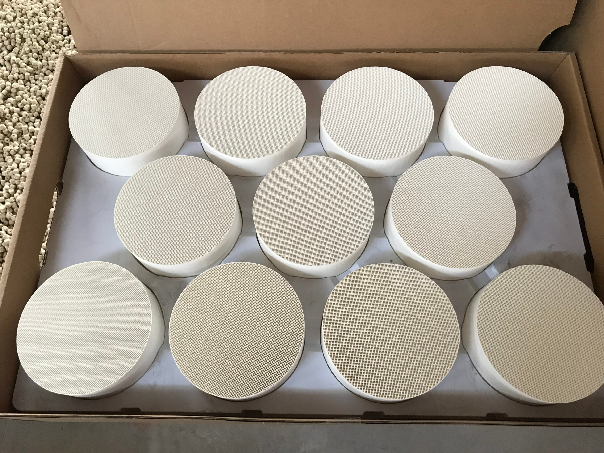
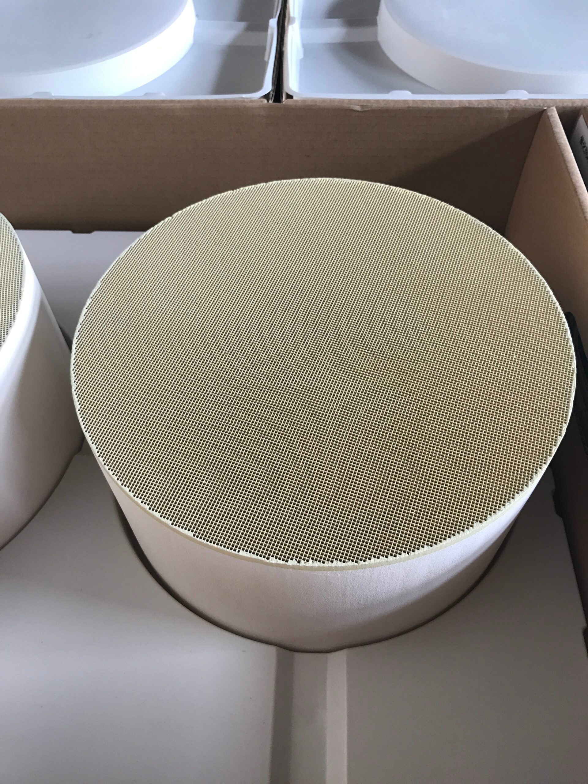
Honeycomb channels guide exhaust past active surfaces while maintaining passages through the substrate. Their size, number, and length influence contact and resistance at the same time.
Changing CPSI, substrate diameter, or length can shift that balance; a cell-density label does not predict the result without the other dimensions. Pressure loss also includes transitions through the converter, so a component-level value may not describe the installed exhaust system.
For a diesel oxidation catalyst, a low-backpressure structure is useful only if the coating and operating temperature still support the intended reactions. The relevant comparison holds the emissions objective constant while assessing different geometry choices at the expected flow range.
If one configuration lowers resistance, its conversion result must be examined at matching conditions. A high-flow claim supported only by an open-channel drawing leaves the chemical half of the design untested.
Flow becomes a design question for us at Hualian Catalyst when a customer provides both the exhaust range and the available envelope. Our DOC information describes a honeycomb intended to reduce pressure loss, with ceramic or metallic substrates, customized dimensions, and selectable CPSI.
Those are variables we can discuss together rather than a ready-made answer for every engine. The customer specification sets the point at which a candidate arrangement can be evaluated.
Check Material, Duty Cycle, and Emissions Together
Material choice changes the thermal and mechanical aspects of a high-flow design. Compared with ceramic alternatives, our metallic option conducts heat more readily and has greater mechanical strength. Tight installations, vibration, and repeated starts bring those properties into the design discussion.
A ceramic option may suit a different layout or duty. Neither material changes the need to assess flow distribution and conversion; it changes the available ways of meeting those requirements within the installation.
The diesel oxidation catalyst system must also be judged over more than one engine state. A part that passes an emissions check at a warm steady load may face different gas temperatures during a cold start.
A geometry that keeps backpressure low at peak flow still needs to offer useful contact at other points in the cycle. Record the temperature and flow attached to each test result. This prevents two favorable numbers from different conditions being presented as though they describe one outcome.
The proposed converter faces two acceptance checks at the stated operating points: pressure loss must remain within its allowance, and the required emission treatment must be demonstrated. Substrate type, size, and CPSI are the variables we can adjust in response.
The answer belongs to the configuration and test conditions, not to one attractive feature in isolation. If packaging forces a change to the flow path, the emission check needs to follow that change.
High flow and emission control are not competing slogans; they are concurrent engineering limits. A workable converter carries the necessary exhaust volume and provides sufficient coated contact under the duty cycle it will actually see. The final specification is credible when pressure and emissions results refer to the same candidate design and the same defined operating conditions.