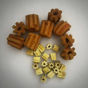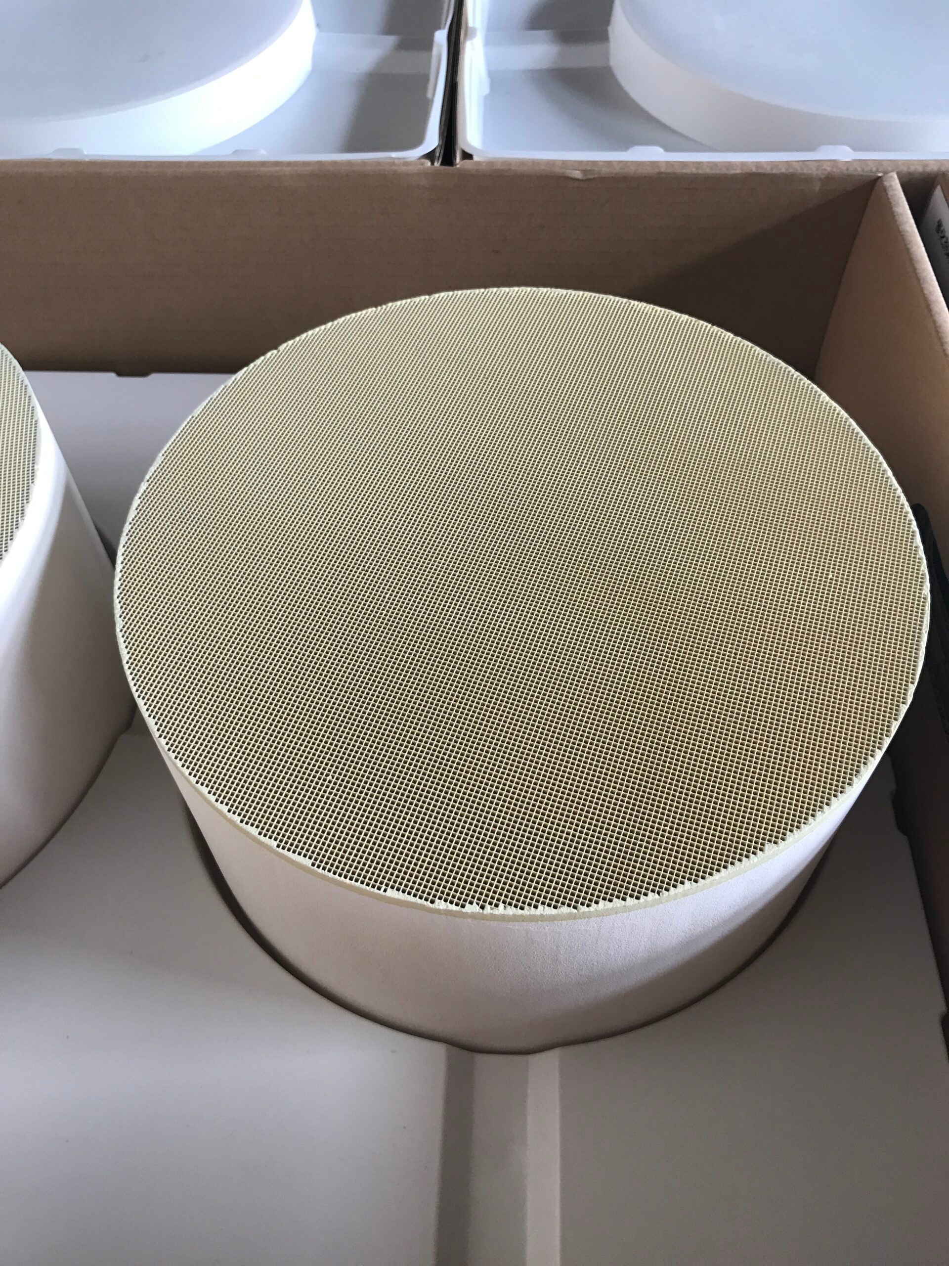
Two catalysts can use similar active chemistry yet expose it to a process stream through very different structures. A honeycomb gives fluid defined channels through a monolithic body; a pellet bed sends fluid through spaces between many separate particles. Contact, pressure loss, heat transfer, and service access all depend on those paths.
A wall-flow diesel particulate filter is a particular honeycomb device with a filtration task, however, not a direct performance twin of an industrial pellet catalyst. Comparing the structures is useful only when the reaction or filtration duty and test conditions are named first.
Compare the Routes Available to the Fluid
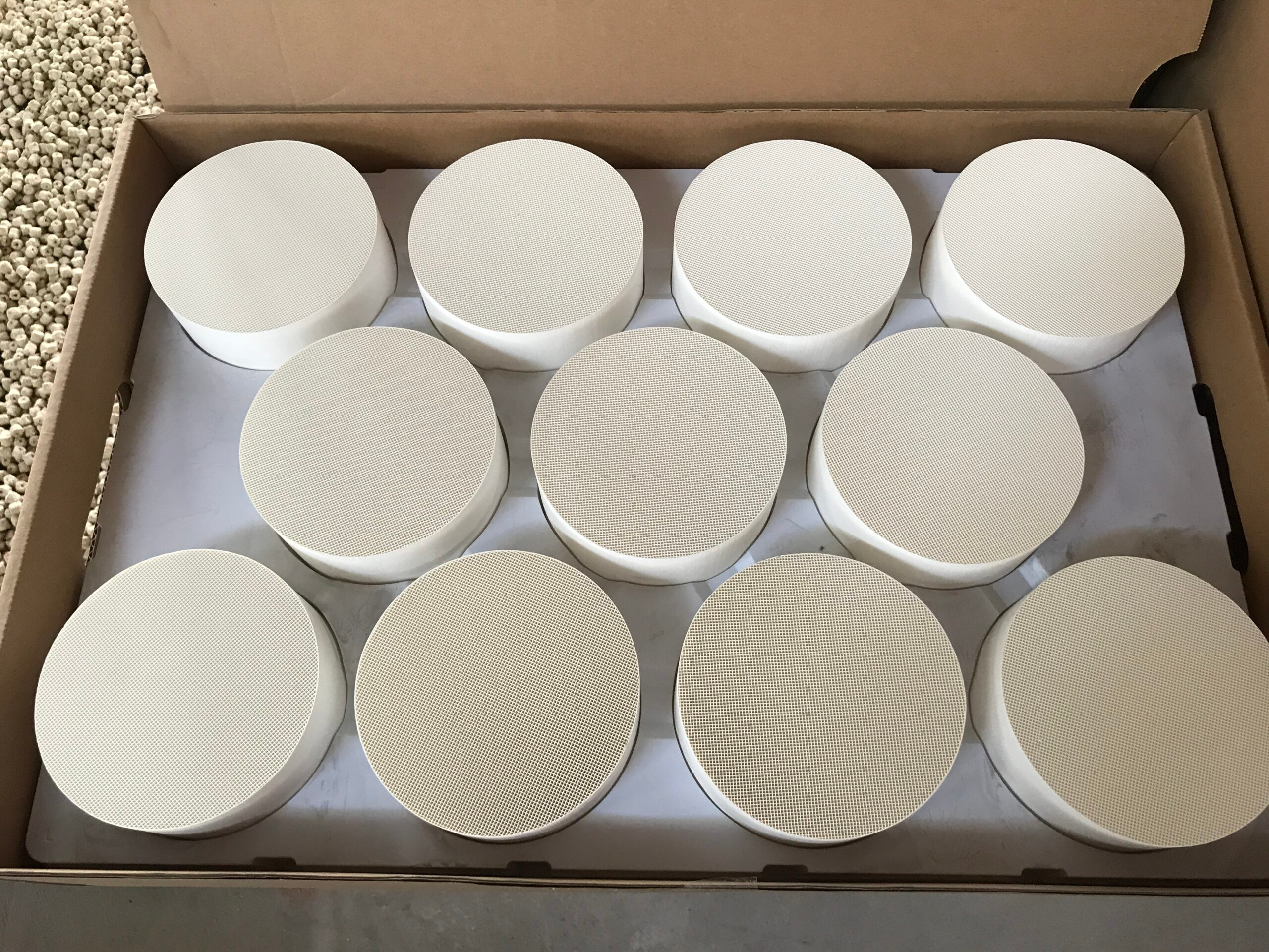
Straight honeycomb channels can carry a high gas flow with comparatively low pressure loss. Coating on channel walls places active material near the moving stream. Channel dimensions and length determine how much surface is available and how long the gas remains in contact.
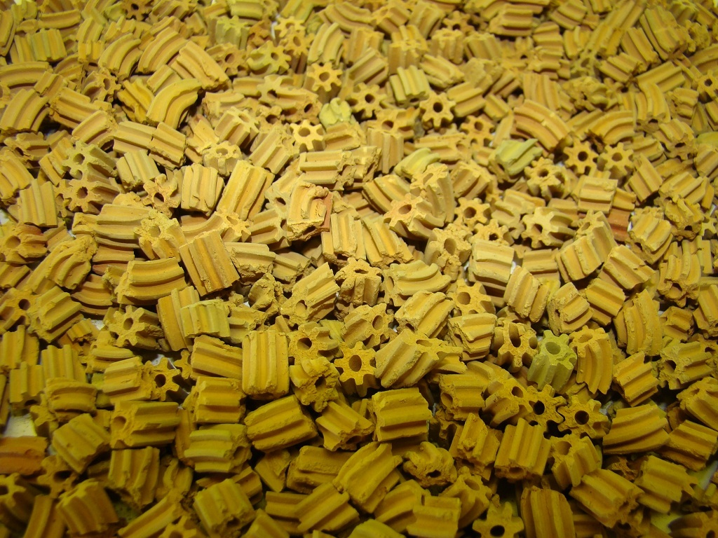
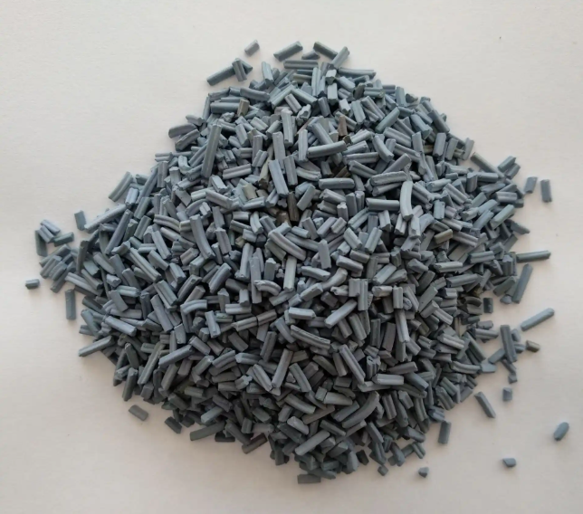
A packed bed has a different path: fluid moves around pellets, and reactants may also diffuse into the porous interiors of the pellets. Pellet size and bed packing affect both contact and resistance. Neither geometry determines conversion without the active formulation and operating conditions.
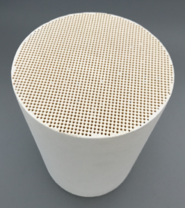
For a diesel particulate filter, the channel arrangement is altered for soot capture. Alternate channel ends are blocked, so exhaust passes through porous walls before leaving. Solid particles are retained as the gas crosses those walls.
That is not the same path as a flow-through catalytic honeycomb, and it is still further from the path through a loose pellet bed. Calling all three “catalyst structures” without specifying the task obscures the engineering difference that matters most.
Pressure-drop comparisons need the same care. A honeycomb’s open channels can be favorable for flow, whereas a packed pellet bed has interparticle resistance. But a wall-flow filter intentionally adds a porous barrier, and its soot load changes with use.
A measured filter pressure loss cannot establish the pressure loss of a separate industrial monolith or pellet reactor. Geometry creates a framework for comparison; matched data produce the actual ranking.
Use the Wall-Flow Honeycomb as a Specific Example
In our Hualian Catalyst wall-flow honeycomb, exhaust crosses porous channel walls and leaves particulate matter behind. Cordierite and SiC are the two material options: the former is described as lightweight, cost-effective, and resistant to thermal shock; the latter has higher thermal conductivity and mechanical strength.
This filter example makes the route through the wall concrete. A pellet-bed comparison instead concerns the spaces between particles, with conversion assessed under its own reaction conditions.
The ceramic choice illustrates why structure and material must be treated as separate variables. Both Cordierite and SiC can form wall-flow filters, yet their thermal and mechanical properties differ.
Channel geometry controls the filtration route; material choice affects how the core responds to heat and stress. A diesel fuel particulate filter also changes condition as soot accumulates and is regenerated. An industrial pellet reactor may have entirely different maintenance and reaction constraints.
The supplied DPF page gives no pellet specifications and no honeycomb-versus-pellet test. We can discuss what our wall-flow design does, but we cannot claim from that page that our honeycomb would outperform a pellet bed in a gas-phase reaction.
A cross-structure comparison would need a shared duty, active material information, flow range, temperature, and measured pressure, conversion, or capture data Without those controls, one product’s strengths become an unfair comparison against missing data.
Define the Comparison Before Ranking Structures
An industrial decision begins by asking whether the objective is catalytic conversion, particulate filtration, or both. For conversion, the comparison may require reaction rate, selectivity, mass transfer, pressure loss, and thermal behavior.
For filtration, capture efficiency, soot capacity, regeneration, and pressure as loading changes become relevant. The same shape word cannot answer both sets of questions. A diesel particulate filter belongs to the second group unless a separate catalytic function and evidence are specified.
Pellet size, bed depth, monolith channel dimensions, and coating thickness can all alter the contact and pressure result. Testing at different flow rates or inlet compositions can reverse an apparent advantage.
That is why a generic claim that honeycombs are always better, or that pellets always provide more useful contact, would be technically weak. The process duty and matched test basis decide which structural feature is valuable.
Our wall-flow filter provides one concrete reference point for that analysis: defined porous-wall passage, Cordierite or SiC material, and soot retention. The missing pellet data must come from the proposed pellet system rather than being inferred from our DPF.
A diesel fuel particulate filter can be selected for its actual filtration task while a separate catalyst-structure comparison proceeds on its own evidence.
Honeycomb and pellet forms differ in flow route and the way active or filtering surfaces are reached. Their performance cannot be ranked responsibly from geometry names alone, especially when one supplied example is a DPF and the other is an unspecified pellet catalyst.
The structural choice turns on the required flow path, allowable pressure loss, and the reaction or capture task assigned to it.